Introduction
What are Surveying Instruments?
Surveying instruments are precision tools used in civil engineering and construction to measure distances, elevations, angles, and alignments accurately. They help engineers establish reference points, transfer levels, set out building layouts, and ensure that construction work is carried out according to design specifications. Proper use of these instruments minimizes errors, improves construction quality, and enhances overall project efficiency.
What This Guide Covers
This guide provides an overview of three essential surveying instruments used in construction:
- Automatic Level – Used to determine differences in elevation and transfer levels accurately during construction.
- Theodolite – A precision instrument used to measure horizontal and vertical angles for alignment, setting out, and surveying.
- Laser Instruments – Modern surveying tools used for distance measurement, leveling, and alignment, offering faster and more accurate results.
In addition to their applications, this guide explains the components, setup procedures, operational methods, maintenance requirements, accessories, storage, transportation, and best practices for each instrument. It serves as a practical reference for site engineers, surveyors, QA/QC engineers, engineering students, and construction professionals who wish to improve measurement accuracy and ensure quality execution on construction projects.
Index
- Important Terminology
Automatic Level
- Setting Up the Instrument
- Checks Before Using the Instrument
- Instrument Operation
- Determining Difference in Elevation
- Station Surveying
- Horizontal Angle Measurement
- Maintenance
- Do’s and Don’ts
- Accessories
- Storage
- Transportation
Theodolite
- Setting Up the Instrument
- Leveling
- Centering Using the Optical Plummet
- Checks Before Using the Instrument
- Instrument Operation
- Horizontal Angle Measurement
- Vertical Angle Measurement
- Maintenance
- Do’s and Don’ts
- Accessories
- Storage
- Transportation
Laser Instruments
- Distance Measuring Instrument
- Multi-Directional Laser Instrument
- Rotating Laser Instrument
Important Terminologies
- Benchmark (BM)
- A reference point established by the Geological Survey of India (GSI) representing the actual elevation of a specific point with respect to Mean Sea Level (MSL).
- Temporary Benchmark (TBM)
- A temporary reference point established on-site and used as the reference for all level measurements during construction.
- Reduced Level (RL)
- The numerical representation of the elevation (altitude) of a point with respect to a benchmark.
- Base Line
- The primary reference line established in one direction on a site from which all other grid lines and marking pillars are set out according to the setting-out drawing.
- Setbacks
- The minimum distance between the building line and the compound wall, or the distance between two building lines.
- PCC (Plain Cement Concrete)
- Plain Cement Concrete.
- GFC (Good for Construction)
- Drawings approved for construction and ready to be executed at the site.
- Grid Lines
- Imaginary lines shown on drawings that generally pass through the center of columns. They are used to locate structural elements such as columns and footings.
- Masonry Line
- A tightly stretched nylon thread used as a reference to indicate direction, alignment, elevation, slope, and other geometrical boundaries.
- Marking Pillars
- Temporary pillars carrying markings representing particular grid lines used for setting out.
- Sunken Slab
- A portion of an RCC slab constructed at a lower level than the surrounding slab, mainly provided in toilets, balconies, and terrace gardens to accommodate drainage and plumbing lines.
- Structural Drop
- A slab portion lowered by 30 mm to 80 mm below the surrounding slab. It is not intended to accommodate plumbing lines.
- Setting-Out Drawing
- A drawing used to locate and align a building accurately on a plot.
- Building Bye-Laws
- Regulations prescribed by the local government authority governing building design and construction, including setbacks, height restrictions, ground coverage, parking requirements, road widths, and related provisions.
- Handrails
- The topmost steel member running along the staircase, providing support for people using the stairs.
- Balusters
- Vertical members of a staircase welded to the base plate fixed on the sides of the staircase.
AUTOMATIC LEVEL
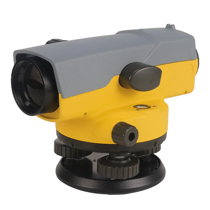
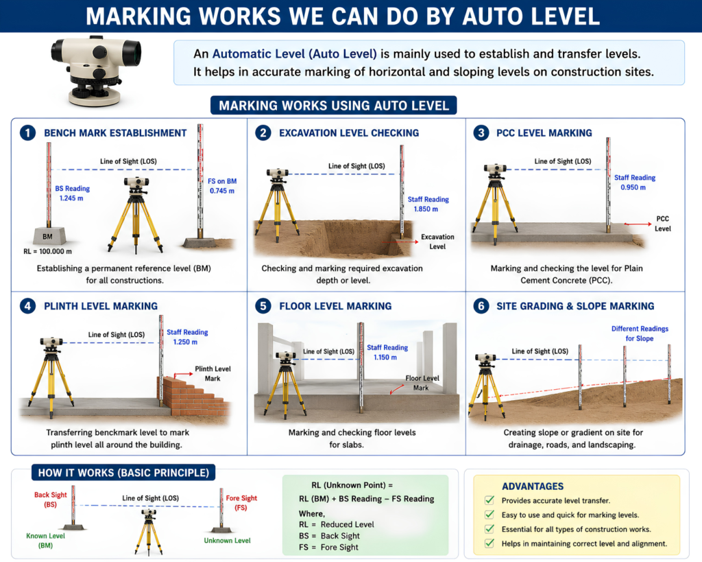
Automatic Level (Auto Level) is an instrument used for construction and engineering leveling.
Main Components of an Auto Level
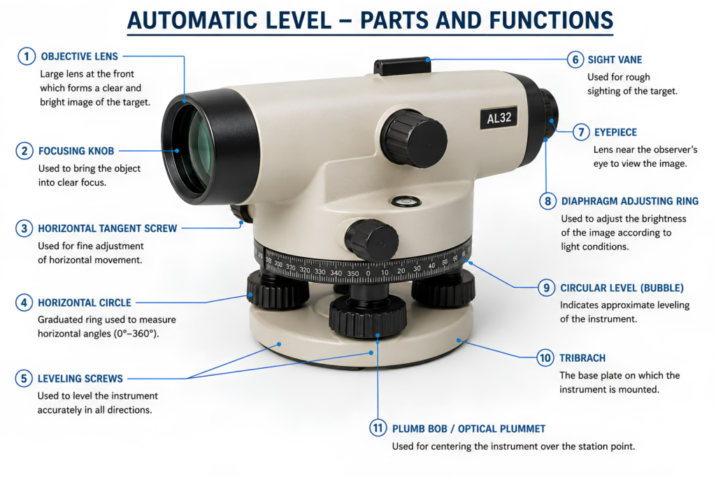
- Telescope
- Erect images
- 20x / 24x / 28x magnification (varies according to the model)
- Shortest focusing distance = 0.4 m
- Focusing screw to obtain a clear image of the leveling staff
- Compensator
- Working range = ±15′
- Setting accuracy depends on the model
- Horizontal circle with angle scale
- Base plate
- Foot screws
- Clamp and tangent screw
- Spirit level (circular bubble)
Setting Up the Instrument
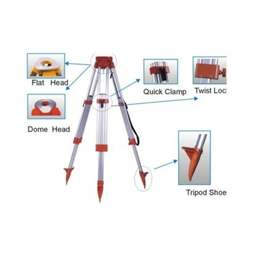
- Unfold the tripod.
- Firmly press the tripod legs into the ground.
- Adjust the tripod head to approximately horizontal.
- Mount the Auto Level on the tripod.
- Tighten the fixing screw securely.
- Level the instrument using the foot screws.
- Bring the circular bubble exactly to the center.
- The instrument is now ready for use.
Checks Before Using the Instrument
Check the Circular Bubble
- Set up and level the instrument.
- Bring the bubble to the center.
- Rotate the instrument by 180°.
- Verify that the bubble remains at the center.
- If it moves, the instrument requires adjustment by an optical instrument specialist.
Check the Compensator
- The compensator is a freely suspended component inside the Auto Level.
- It automatically compensates for minor leveling errors.
- Tap the instrument gently.
- The image should move slightly and then stabilize.
- If the image does not stabilize, the compensator requires servicing.
Check the Telescope
- Ensure the image is sharp and clear.
- Remove parallax by properly adjusting:
- Eyepiece
- Focusing knob
Instrument Operation
- Set up the instrument.
- Level the instrument accurately.
- Focus the eyepiece.
- Focus on the leveling staff.
- Remove parallax.
- Take the staff reading.
Difference in Elevation
The Auto Level is used to determine the difference in elevation between two points.
Procedure:
- Take the Back Sight (BS) reading.
- Take the Fore Sight (FS) reading.
- Calculate the difference in level.
General relationship:
Difference in Elevation = BS − FS
Station Surveying
Station surveying is carried out by taking observations from different instrument stations to determine levels and elevations over an area.
Typical observations include:
- Back Sight (BS)
- Intermediate Sight (IS)
- Fore Sight (FS)
These readings are used to calculate the Reduced Levels (RLs) of different points.
Horizontal Angle Measurement
The Auto Level has an inbuilt horizontal angle scale.
Procedure:
- Set up and level the instrument.
- Align the vertical cross hair with the first point (Point A).
- Set the horizontal circle reading to 0°.
- Lock the horizontal scale.
- Rotate the telescope to the second point (Point B).
- Read the horizontal angle displayed on the scale.
Note: It is generally advised not to use an Auto Level for precise angle measurements. A Theodolite is recommended for accurate angle measurement.
Maintenance
- Keep the instrument clean.
- Protect it from dust and moisture.
- Clean optical parts only with lens tissue.
- Store the instrument in its carrying case.
- Periodically check calibration.
- Avoid shocks and vibrations.
Do’s and Don’ts
Do’s
- Carry the instrument carefully.
- Level the instrument accurately.
- Keep lenses clean.
- Use the carrying case after work.
- Check calibration regularly.
Don’ts
- Do not touch optical lenses with fingers.
- Do not expose the instrument to rain.
- Do not drop or mishandle the equipment.
- Do not force adjustment screws.
- Do not leave the instrument unattended on site.
Accessories
Typical accessories supplied with an Auto Level include:
- Tripod
- Leveling Staff
- Carrying Case
- Adjustment Tools
- Plumb Bob (where applicable)
Storage
- Store in a clean and dry place.
- Keep inside the protective carrying case.
- Avoid excessive heat and humidity.
- Remove dust before storage.
Transportation
- Always transport the instrument in its protective case.
- Lock all moving parts before transportation.
- Handle carefully to avoid impacts and vibrations.
- Never carry the instrument mounted on the tripod.
THEODOLITE
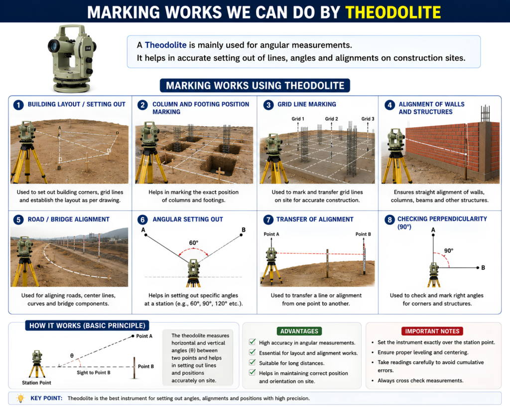
A Theodolite is a precision surveying instrument used to measure horizontal and vertical angles accurately. It is widely used for setting out, alignment, traversing, and construction surveys.
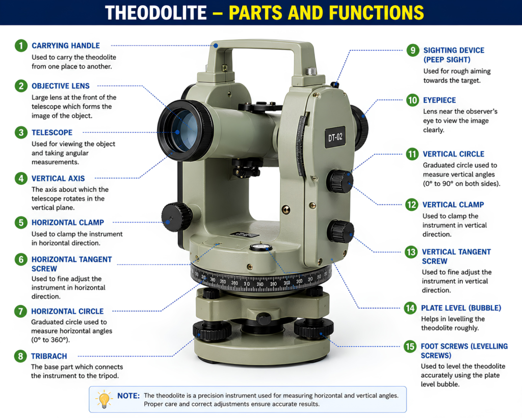
Main Components of a Theodolite
- Telescope
- Eyepiece
- Objective lens
- Horizontal circle
- Vertical circle
- Horizontal clamp
- Horizontal tangent screw
- Vertical clamp
- Vertical tangent screw
- Plate level
- Circular bubble
- Tribrach
- Leveling (Foot) screws
- Optical plummet
- Display panel (Digital Theodolite)
- Battery compartment
- Handle
Setting Up the Instrument
Follow the steps below to correctly set up the Theodolite:
Step 1: Position the Tripod
- Spread the tripod legs evenly.
- Position the tripod approximately over the survey station.
- Ensure the tripod head is nearly horizontal.
- Firmly press the tripod legs into the ground.
Step 2: Mount the Instrument
- Place the Theodolite on the tripod head.
- Tighten the central fixing screw securely.
- Ensure the instrument is firmly fixed.
Leveling
Leveling ensures that the instrument is perfectly horizontal before taking observations.
Procedure
- Center the circular bubble using the tripod legs.
- Adjust two foot screws simultaneously to move the plate bubble.
- Rotate the instrument by 90°.
- Adjust the third foot screw.
- Repeat the process until the bubble remains at the center in all directions.
- Rotate the instrument through 360° to confirm that the bubble remains centered.
Centering Using the Optical Plummet
The Optical Plummet is used to position the instrument exactly over the survey station.
Procedure
- Look through the optical plummet.
- Locate the ground reference point.
- Move the tripod carefully until the point appears near the center.
- Use the tribrach shifting screws (if available) for fine adjustment.
- Repeat leveling after centering.
- Ensure both leveling and centering are correct before starting observations.
Checks Before Using the Instrument
Before commencing work, verify the following:
Circular Bubble
- Bubble should remain centered after rotating the instrument.
Plate Bubble
- Bubble should remain centered after leveling.
Optical Plummet
- Ensure the plummet is exactly over the station point.
Telescope
- Image should be clear and properly focused.
- Remove parallax before observations.
Battery
- Check battery level.
- Replace or recharge if necessary.
Display
- Verify that the LCD display is functioning properly.
Instrument Operation
- Set up the instrument.
- Level the instrument accurately.
- Center over the survey station.
- Focus the eyepiece.
- Focus the target.
- Remove parallax.
- Lock the horizontal clamp.
- Use tangent screws for precise alignment.
- Record horizontal and vertical angle readings.
Horizontal Angle Measurement
Procedure
- Set up and level the instrument.
- Sight the first point (Point A).
- Set the horizontal angle reading to 0°00′00″ (or note the initial reading).
- Lock the horizontal circle.
- Rotate the telescope towards Point B.
- Precisely align the cross hair using the tangent screw.
- Read the horizontal angle displayed.
Repeat the observation for improved accuracy.
Vertical Angle Measurement
Procedure
- Level the instrument.
- Sight the target.
- Focus accurately.
- Remove parallax.
- Read the vertical angle displayed.
- Record whether the angle is above or below the horizontal plane.
Maintenance
- Keep the instrument clean.
- Clean lenses only with a lens cloth.
- Store in its protective carrying case.
- Keep away from moisture.
- Avoid direct sunlight for prolonged periods.
- Recharge batteries regularly.
- Send for calibration periodically.
Do’s and Don’ts
Do’s
- Carry the instrument carefully.
- Ensure accurate leveling before use.
- Remove parallax before taking readings.
- Transport in the protective case.
- Keep the instrument clean and dry.
Don’ts
- Do not carry the instrument mounted on the tripod.
- Do not force clamps or tangent screws.
- Do not expose the instrument to rain.
- Do not touch optical lenses with bare fingers.
- Do not store the instrument in damp conditions.
LASER INSTRUMENTS
Laser instruments are modern surveying and construction tools that use laser technology to provide accurate measurements, alignment, leveling, and layout work. They improve accuracy, reduce manual effort, and increase productivity on construction sites.
The three commonly used laser instruments are:
- Distance Measuring Instrument (Laser Distance Meter)
- Multi-Directional Laser Instrument
- Rotating Laser Instrument

Distance Measuring Instrument (Laser Distance Meter)
A Laser Distance Meter is used to measure distances quickly and accurately using a laser beam.
Applications
- Measuring room dimensions
- Building layout
- Interior works
- Quantity estimation
- Elevation measurements
- Site inspections
Main Components
- Laser emitter
- Display screen
- Keypad
- Measurement button
- Battery compartment
- Memory function
Operating Procedure
- Switch ON the instrument.
- Select the required measurement unit (m, ft, in).
- Place the rear of the instrument against the reference surface.
- Aim the laser at the target.
- Press the measurement button.
- Read the displayed distance.
- Record the measurement if required.
Advantages
- Fast measurements
- High accuracy
- Easy to operate
- Stores measurement values
- Reduces manual errors
Multi-Directional Laser Instrument
A Multi-Directional Laser Instrument projects horizontal, vertical, and cross laser lines simultaneously.
Applications
- Wall alignment
- Tile fixing
- Ceiling installation
- Plumbing work
- Electrical layout
- Door and window installation
- Interior finishing works
Features
- Horizontal laser line
- Vertical laser line
- Cross line projection
- Self-leveling mechanism
- Compact design
Operating Procedure
- Place the instrument on a stable surface or tripod.
- Switch ON the instrument.
- Allow the instrument to self-level.
- Select the required laser mode.
- Align work using the projected laser lines.
- Switch OFF after completion.
Advantages
- High accuracy
- Easy alignment
- Saves time
- Suitable for interior works
- Reduces marking errors
Rotating Laser Instrument
A Rotating Laser Instrument projects a continuously rotating laser beam to create a complete 360° horizontal reference plane.
It is mainly used for leveling over long distances.
Applications
- Building construction
- Road construction
- Foundation leveling
- Earthwork
- Large area leveling
- Drainage works
- Concrete floor leveling
Main Components
- Rotating laser head
- Control panel
- Self-leveling mechanism
- Laser receiver
- Tripod
- Battery
Operating Procedure
- Set up the tripod.
- Mount the rotating laser instrument.
- Switch ON the instrument.
- Allow the instrument to self-level automatically.
- Set the required rotation speed.
- Use the laser receiver for long-distance measurements.
- Record the required levels.
- Switch OFF and store the instrument safely after use.
Advantages
- Covers a 360° working area
- Highly accurate
- Suitable for long-distance leveling
- Saves manpower
- Increases productivity
- Ideal for large construction projects
Maintenance of Laser Instruments
- Keep the instrument clean and dry.
- Clean laser windows with a soft cloth.
- Avoid dropping or subjecting the instrument to impacts.
- Recharge or replace batteries as required.
- Store in the protective carrying case.
- Periodically calibrate the instrument.
- Protect the instrument from dust and moisture.
Do’s and Don’ts
Do’s
- Read the user manual before operating the instrument.
- Verify calibration before use.
- Use a stable tripod or surface.
- Store the instrument in its carrying case.
- Handle with care during transportation.
Don’ts
- Do not look directly into the laser beam.
- Do not expose the instrument to heavy rain or water.
- Do not drop the instrument.
- Do not operate with a low battery.
- Do not use a damaged instrument.
Accessories
Typical accessories supplied with laser instruments include:
- Carrying Case
- Tripod
- Laser Receiver
- Target Plate
- Batteries
- Charger
- User Manual
Storage
- Store in a clean and dry location.
- Keep inside the protective carrying case.
- Avoid exposure to direct sunlight and excessive heat.
- Remove batteries if the instrument will not be used for a long period.
Transportation
- Always transport the instrument in its carrying case.
- Lock all movable parts before transportation.
- Protect from shocks and vibrations.
- Never transport the instrument while mounted on the tripod.
End of Chapter – Surveying Instruments
Frequently Asked Questions (FAQs)
1. What is an Automatic Level used for?
An Automatic Level is a surveying instrument used to determine differences in elevation between points. It is commonly used in construction for leveling, site layout, and transferring benchmark levels.
2. What is the purpose of a Theodolite?
A Theodolite is a precision surveying instrument used to measure horizontal and vertical angles. It is widely used for alignment, setting out, and construction surveying.
3. What are Laser Instruments used for in construction?
Laser instruments are used for accurate distance measurement, leveling, alignment, and layout work. They improve efficiency and reduce manual measurement errors on construction sites.
4. What checks should be performed before using surveying instruments?
Before use, ensure the instrument is properly leveled, verify the bubble level, remove parallax, inspect the optics, check the battery (for digital instruments), and confirm calibration for accurate measurements.
5. How should surveying instruments be maintained?
Surveying instruments should be cleaned regularly, stored in their protective carrying case, protected from dust, moisture, and impacts, and calibrated periodically to maintain measurement accuracy.