
Introduction
Foundation work begins with accurate marking. It is one of the most important activities on any construction site. A small error at this stage can lead to misaligned PCC, columns, incorrect footing locations, expensive rework, and project delays.
Once the PCC has gained sufficient strength, the next activity is footing and column marking. This process is one of the most critical stages of foundation construction because it determines the exact position of every footing, pedestal, tie beam, and column.
Therefore, the survey and QA/QC teams must verify every marking before reinforcement and shuttering begin. Even a minor error can lead to structural problems, alignment issues, and expensive rework.
After completing the footing or slab concreting, the next important activity is starter marking. This process ensures that every column, wall, or pedestal is cast in the correct position and alignment. Since the starter acts as a reference for fixing column shuttering, accurate marking is essential.
Therefore, engineers must carefully transfer the grid lines, verify dimensions, and inspect the markings before shuttering begins. A small error at this stage can affect the alignment of the entire structure.
In this guide, you will learn the purpose of PCC Marking, footing and column marking & starter marking, the step-by-step procedure, quality inspection requirements, and practical site tips followed by experienced engineers.
What Is PCC Marking?
Plain Cement Concrete (PCC) marking is the process of transferring the building layout onto the PCC surface before reinforcement work begins.
First, PCC is laid over the excavated soil to create a clean, level, and stable working platform. Next, engineers mark the footing locations, grid lines, and center lines on this surface according to the approved structural drawings.
As a result, every footing and column is constructed at the correct location.
The PCC area depends on the foundation type.
- Raft Foundation: PCC covers the complete excavated area.
- Isolated Footing: PCC is laid only below each footing.
Besides providing a level surface, PCC prevents fresh structural concrete from coming into direct contact with soil.
Why Is PCC Marking Important?
Accurate PCC marking improves both construction quality and structural accuracy.
It helps engineers:
- Fix footing locations correctly.
- Transfer grid lines accurately.
- Establish column center lines.
- Maintain proper building alignment.
- Avoid construction errors.
- Reduce costly rework.
- Improve the accuracy of reinforcement and shuttering work.
Furthermore, proper marking speeds up foundation construction because every activity follows a clearly established layout.
Objectives of PCC Marking
The primary objective of PCC marking is to establish an accurate reference for foundation construction.
Specifically, it helps to:
- Mark footing boundaries.
- Identify footing centers.
- Transfer building grid lines.
- Maintain structural dimensions.
- Establish reference points for survey work.
- Ensure all construction follows the GFC drawings.
Consequently, every structural member is built in its intended position.
Step-by-Step PCC Marking Procedure
The following procedure is commonly followed on construction projects.
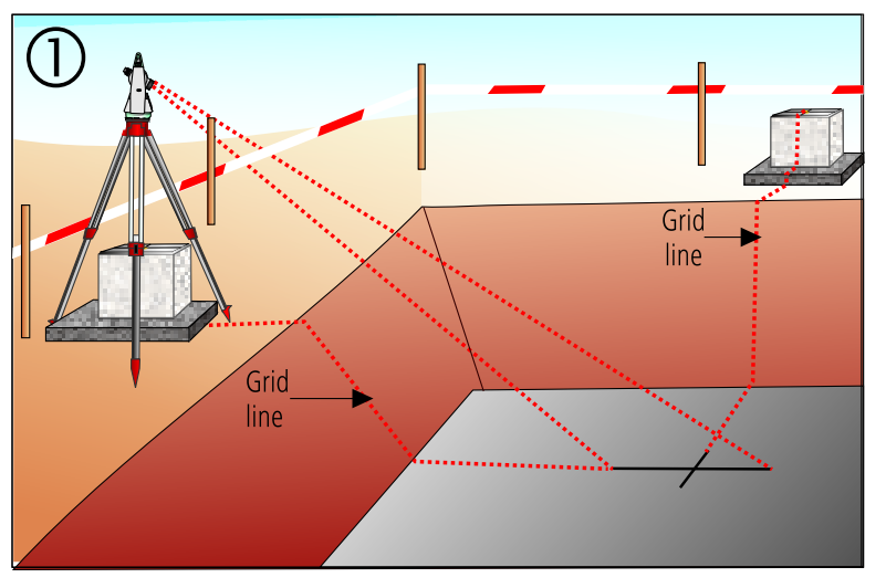
Step 1: Transfer the Grid Lines
First, transfer the building grid lines from the survey control points to the excavation using a theodolite.
These grid lines establish:
- Footing locations
- Footing center points
- Building alignment
- Structural axes
After transferring the grid lines, compare them with the approved GFC drawings. This verification helps eliminate layout errors before PCC work begins.
Step 2: Identify the PCC Area
Next, identify the area where PCC will be laid.
Use the footing layout drawing to determine the required dimensions.
In most projects, PCC extends 75 mm beyond the footing on all sides. However, always follow the structural drawings if they specify a different projection.
This extra width provides sufficient space for reinforcement fixing and shuttering activities.
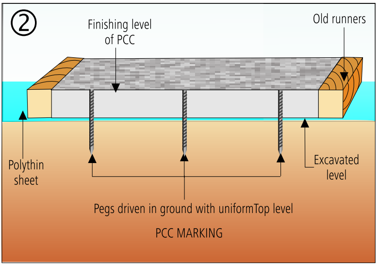
Step 3: Fix Steel Pegs
After identifying the PCC area, fix steel pegs into the excavated ground.
Normally, engineers use:
- 10 mm reinforcement bars
- Length between 150 mm and 200 mm
The top of every peg represents the finished PCC level.
Alternatively, concrete button marks may be used instead of steel pegs.
Step 4: Establish the PCC Level
Once the pegs are installed, establish the final PCC level using an Auto Level.
The level should always match:
- Temporary Benchmark (TBM)
- Approved GFC drawings
- Required PCC thickness
As a result, the entire PCC surface remains level and uniform.
Step 5: Lay the Polythene Sheet (If Required)
Some projects require a polythene sheet before placing PCC.
The sheet prevents cement slurry from seeping into the soil. It also helps maintain the concrete’s water-cement ratio and improves the overall quality of the PCC layer.
Always follow the project specifications before placing the sheet.
Quality Inspection Checklist for PCC Marking
Before PCC concreting begins, the QA/QC engineer should inspect every marking carefully.
Survey Checks
✔ Verify the transferred grid lines.
✔ Confirm the footing layout matches the drawings.
✔ Check the location of every footing.
✔ Ensure center lines are correctly established.
Level Checks
✔ Check that all steel pegs are at the same elevation.
✔ Verify the finished PCC level with the TBM.
✔ Confirm the required PCC thickness.
Dimensional Checks
✔ Measure the PCC dimensions.
✔ Confirm the PCC extends beyond the footing.
✔ Verify the offsets according to the footing layout drawing.
General Checks
✔ Ensure the excavation is clean.
✔ Confirm loose soil has been removed.
✔ Check that the polythene sheet is placed correctly, if required.
✔ Obtain survey and QA/QC approval before concreting.
Common Mistakes During PCC Marking
Even experienced site teams can make mistakes. However, most errors are easy to avoid with proper planning.
Some common mistakes include:
- Incorrect transfer of grid lines.
- Uneven PCC levels.
- Wrong footing dimensions.
- Missing survey verification.
- Improper peg spacing.
- Failure to check the TBM level.
- PCC extending less than the specified projection.
- Starting concreting without QA/QC approval.
Therefore, always perform a final inspection before placing concrete.
Best Practices for PCC Marking
To achieve accurate results, follow these industry best practices:
- Use calibrated surveying instruments.
- Verify grid lines before marking.
- Cross-check all dimensions with the GFC drawings.
- Maintain a permanent survey reference point.
- Check PCC levels using an Auto Level.
- Record all inspection observations.
- Obtain approval before concreting.
- Protect the completed markings until reinforcement work starts.
Following these practices improves construction quality and reduces the risk of costly rework.
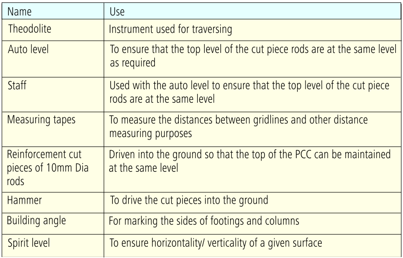
What Is Footing and Column Marking?
Footing and column marking is the process of transferring the building grid lines, footing boundaries, and column center lines onto the finished PCC surface.
After the survey team establishes the grid lines, engineers mark the footing size, column location, and tie beam position according to the approved Good for Construction (GFC) drawings.
As a result, every structural member is constructed in its correct location.
Why Is Footing and Column Marking Important?
Accurate marking plays a major role in maintaining the structural integrity of a building.
It helps to:
- Position every footing correctly.
- Maintain the building grid system.
- Align columns accurately.
- Establish tie beam locations.
- Reduce construction errors.
- Prevent rework and delays.
- Ensure compliance with approved drawings.
Furthermore, correct marking improves coordination between the survey, reinforcement, shuttering, and concreting teams.
Objectives of Footing and Column Marking
The primary objective is to ensure that every footing and column is constructed exactly as designed.
Specifically, it helps to:
- Transfer building grid lines.
- Mark footing boundaries.
- Establish column center lines.
- Locate tie beams accurately.
- Verify structural dimensions.
- Maintain alignment throughout construction.
Consequently, all structural members remain within the specified tolerances.
Step-by-Step Footing and Column Marking Procedure
The following procedure is commonly followed on construction sites.
Step 1: Transfer Grid Lines onto the PCC
First, transfer the building grid lines from the survey control points onto the finished PCC using a theodolite.
After completing the transfer, compare the grid lines with the approved GFC drawings.
This verification ensures that the layout is correct before any further marking begins.
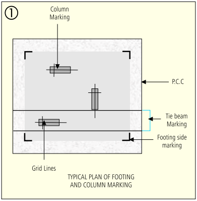
Step 2: Mark the Footing Boundaries
Next, mark the footing boundaries according to the approved footing layout drawing.
Clearly indicate:
- Footing edges
- Footing center lines
- Tie beam locations
- Reference axes
Use a thin string line, approximately 1 mm thick, to maintain straight and accurate markings.
In addition, ensure that every line is clearly visible before proceeding.
Step 3: Mark the Column Position
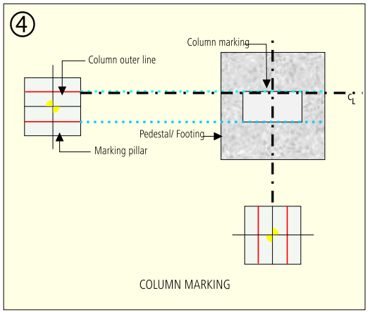
After marking the footing, transfer the column center line from the survey reference or marking pillar.
Then, measure the required offsets from the center line to establish the exact column dimensions.
Always compare these dimensions with the approved structural drawings before finalizing the marking.
Step 4: Fix Nails at Reference Points
Drive steel nails at important grid intersections and reference points.
These nails serve as permanent control points during reinforcement fixing and shuttering.
Moreover, they help engineers verify alignment both before and after concreting.
Step 5: Use a Right-Angle Template
Now, mark the column corners using a right-angle template.
This simple tool helps achieve accurate 90-degree corners and prevents layout errors.
As a result, the footing and column remain perfectly square.
Step 6: Check the Diagonals
After completing the marking, measure both diagonals of every footing.
Equal diagonals confirm that the footing is perfectly square or rectangular.
If the diagonal measurements differ, correct the layout before moving to the next activity.
Step 7: Transfer Grid Lines onto the Shuttering
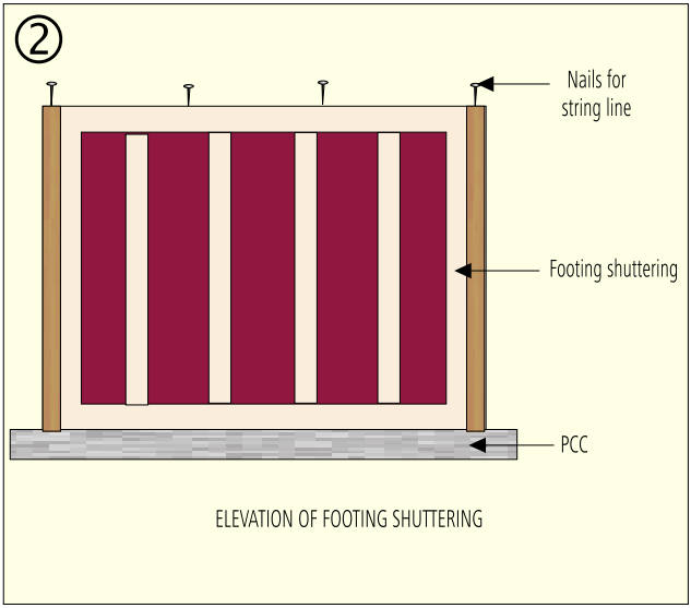
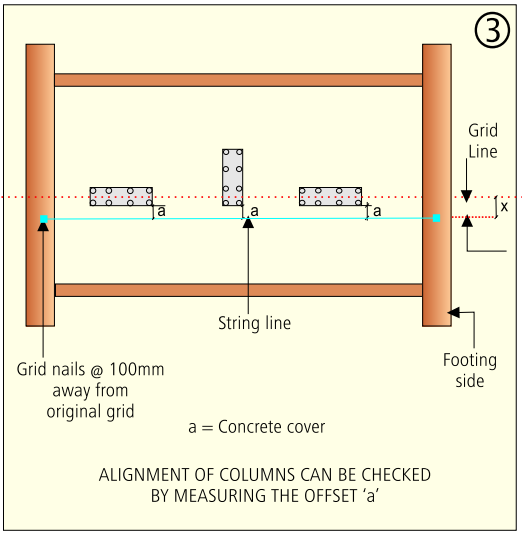
Once reinforcement and shuttering are complete, transfer the grid lines to the footing shuttering. Then, measure the required offsets. Finally, confirm the distance between the shutter and the outer face of the column reinforcement.
Quality Inspection Checklist for Footing and Column Marking
Before reinforcement or concreting begins, the QA/QC engineer should inspect the complete marking.
Survey Check
✔ Please verify the transferred grid lines.
✔ Confirm the grid spacing matches the drawings.
✔ Check the footing location.
✔ Verify the column center lines.
✔ Confirm the reference axes.
Dimensional Checks
✔ Measure the footing length and width.
✔ Verify the column dimensions.
✔ Check tie beam locations.
✔ Confirm all required offsets.
✔ Compare every dimension with the GFC drawings.
Alignment Checks
✔ Check the straightness of the grid lines.
✔ Verify column alignment.
✔ Ensure all corners are at 90 degrees.
✔ Confirm the string line alignment.
Diagonal Checks
✔ Measure both footing diagonals.
✔ Measure column diagonals where applicable.
✔ Confirm equal diagonal measurements.
Reference Checks
✔ Verify the marking pillars.
✔ Check the survey control points.
✔ Confirm nail positions.
✔ Ensure no marking has shifted before reinforcement starts.
Curing of Marking
Sometimes, engineers use cement paste to make permanent markings on the PCC surface.
After completing the marking:
- Cover the markings with Hessian cloth or gunny bags.
- Keep the surface moist through proper curing.
- Protect the markings until reinforcement work begins.
This process prevents the markings from fading or becoming damaged during site activities.
Common Mistakes During Footing and Column Marking
Although the procedure appears simple, several mistakes can affect the accuracy of the structure.
Common mistakes include:
- Incorrect transfer of grid lines.
- Wrong footing dimensions.
- Incorrect column offsets.
- Unequal diagonal measurements.
- Poor alignment of string lines.
- Missing reference nails.
- Failure to verify dimensions with the drawings.
- Skipping survey approval before reinforcement.
Therefore, always complete a final inspection before proceeding.
Best Practices for Accurate Marking
Experienced engineers follow these practices to improve construction quality:
- Use calibrated survey equipment.
- Verify grid lines before marking.
- Measure every dimension twice.
- Check footing diagonals immediately after marking.
- Use a right-angle template for all corners.
- Protect markings until reinforcement is complete.
- Maintain permanent survey reference points.
- Record all inspection observations.
- Obtain approval from both the survey and QA/QC teams before reinforcement starts.
Following these practices reduces errors, improves productivity, and ensures compliance with project specifications.
What Is Starter Marking?
Starter marking is the process of marking the exact location of a column, pedestal, or wall on a completed footing or slab before fixing the shuttering.
The starter provides a permanent reference for positioning the shutter accurately. As a result, the column is cast exactly according to the approved Good for Construction (GFC) drawings.
Proper starter marking improves construction accuracy and minimizes alignment errors during concreting.
Why Is Starter Marking Important?
Accurate starter marking offers several advantages during construction.
It helps to:
- Position columns correctly.
- Maintain structural alignment.
- Fix shuttering accurately.
- Reduce dimensional errors.
- Prevent column shifting during concreting.
- Improve construction quality.
- Minimize costly rework.
Furthermore, it ensures that upper-floor columns align perfectly with the columns below.
Objectives of Starter Marking
The main objective of starter marking is to establish an accurate reference for column shuttering.
Specifically, it helps to:
- Transfer grid lines onto the footing or slab.
- Mark column dimensions accurately.
- Maintain column alignment.
- Verify distances between columns.
- Ensure compliance with the GFC drawings.
Consequently, the entire structural frame remains within the specified tolerances.
Starter Marking on Footings
The following procedure is generally followed after footing concreting.
Step 1: Transfer the Grid Lines
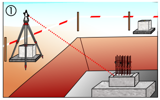
First, transfer the building grid lines onto the completed footing or pedestal using a theodolite.
Afterward, compare the transferred grid lines with the approved GFC drawings to confirm their accuracy.
Step 2: Mark the Column Size
Next, mark the exact column dimensions on the footing.
The marked outline indicates where the starter template and column shuttering will be fixed.
Therefore, ensure that all dimensions match the approved structural drawings.
Step 3: Verify the Grid Distances
Before finalizing the marking, measure the distances between adjacent grids.
Then, compare the measurements with the approved layout drawing.
If any discrepancy is found, correct it immediately before proceeding.
Step 4: Mark the Starter
After verification, mark the starter according to:
- Footing layout drawing
- Column layout drawing
- Approved GFC drawings
Finally, recheck all measurements before approving the marking.
Starter Marking on Slabs
The procedure changes slightly when marking starters on upper floors.
Step 1: Drop a Plumb Line
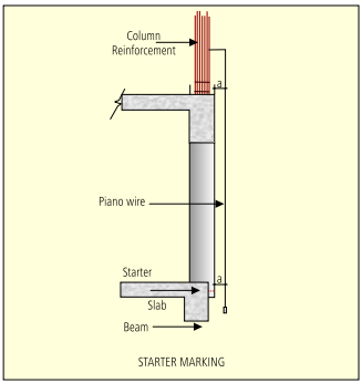
After the slab concrete has gained sufficient strength, drop a plumb line from the outer column or lift wall.
This helps transfer the alignment from the lower floor to the current floor.
Step 2: Check the Plumb
Next, compare the plumb line with the starter position of the column below.
This step ensures that the new column remains perfectly aligned with the existing structure.
Step 3: Transfer the Column Line
Using the theodolite and adjustment piece, transfer the outer column line from the building marking pillars onto the slab.
This creates accurate control points for further marking.
Step 4: Establish Control Points
After transferring the column line, establish permanent control points on the slab.
These points act as references for marking the remaining columns.
Step 5: Mark the Remaining Grid Lines
Using the established control points, measure and mark the remaining grid lines with a measuring tape.
Afterward, verify every measurement before proceeding.
Step 6: Confirm All Dimensions
Finally, compare the marked distances with the approved drawings.
Only after verification should the starter marking be approved.
Starter Marking Process
Once the control lines are established, complete the following steps.
Ensure a Level Surface
First, check that the concrete surface around the reinforcement is clean, level, and properly finished.
An uneven surface can affect the accuracy of the starter.
Transfer the Center Lines
Next, transfer all required center lines onto the concrete surface.
Use the approved survey references to avoid errors.
Draw the Starter Lines
Using the following tools:
- Pencil
- Steel scale
- Right-angle square
draw the starter outline accurately.
Additionally, ensure that every line is clear and easy to identify.
Cut a Permanent Groove
After completing the marking, cut a narrow groove along the marked lines using a hacksaw blade.
The groove prevents the marking from fading during reinforcement fixing and shuttering work.
As a result, the starter remains visible until concreting is complete.
Quality Inspection Checklist for Starter Marking
Before fixing the shuttering, the QA/QC engineer should inspect every starter carefully.
Dimensional Checks
✔ Verify the starter dimensions.
✔ Compare all measurements with the GFC drawings.
✔ Confirm the required offsets.
Alignment Checks
✔ Check the alignment of every starter.
✔ Verify the column center lines.
✔ Ensure proper positioning with adjacent columns.
Diagonal Checks
✔ Measure the starter diagonals.
✔ Confirm that opposite diagonals are equal.
Grid Line Checks
✔ Verify the transferred grid lines.
✔ Check the spacing between adjacent columns.
✔ Confirm the survey reference points.
Post-Concreting Checks
After concreting:
✔ Check the alignment of all starters using a string line.
✔ Measure the distance between adjacent starters.
✔ Confirm that no starter has shifted during concreting.
✔ Verify the vertical alignment before fixing the next floor shuttering.
Common Mistakes During Starter Marking
Although the procedure is straightforward, several mistakes can reduce construction quality.
Some common errors include:
- Incorrect transfer of grid lines.
- Wrong column dimensions.
- Poor alignment with the lower floor.
- Unequal diagonal measurements.
- Missing groove along the starter.
- Failure to verify offsets.
- Starting shuttering without QA/QC approval.
- Ignoring survey verification.
Therefore, every starter should undergo a final inspection before shuttering begins.
Best Practices for Starter Marking
To achieve consistent accuracy, follow these industry best practices:
- Use calibrated surveying instruments.
- Verify all grid lines before marking.
- Measure every dimension twice.
- Confirm column alignment with the lower floor.
- Cut a permanent groove after marking.
- Protect the markings until shuttering starts.
- Maintain accurate survey control points.
- Record inspection observations.
- Obtain approval from the survey and QA/QC teams before fixing shuttering.
Following these practices improves construction quality and reduces the risk of alignment errors.
Frequently Asked Questions (FAQs)
1. What is PCC marking in construction?
PCC marking is the process of transferring building grid lines, footing locations, and center lines onto the Plain Cement Concrete (PCC) surface before reinforcement and footing work begins. It ensures that all structural elements are constructed according to the approved Good for Construction (GFC) drawings.
2. Why is Plain Cement Concrete (PCC) provided before footing construction?
PCC provides a clean, level, and stable working platform for reinforcement fixing and shuttering. It also prevents structural concrete from coming into direct contact with soil, reducing contamination and improving the quality of the foundation.
3. How much should PCC extend beyond the footing?
In most construction projects, PCC extends 75 mm beyond the footing on all sides. However, the exact projection should always follow the approved structural drawings or project specifications.
4. Which surveying instruments are used for PCC, footing, column, and starter marking?
The commonly used instruments include:
- Theodolite
- Auto Level
- Total Station (where applicable)
- Measuring Tape
- Plumb Bob
- String Line
- Right-Angle Square
- Steel Scale
These instruments help achieve accurate layout, level, and alignment.
5. Why are grid lines important in foundation marking?
Grid lines act as the primary reference for locating footings, columns, tie beams, and walls. Accurate grid transfer ensures that every structural member is constructed in the correct position and maintains the overall building alignment.
6. Why are footing diagonals checked before concreting?
Checking the diagonals confirms that the footing is perfectly square or rectangular. Equal diagonal measurements indicate accurate marking and help prevent alignment issues during reinforcement and concreting.
7. What is the purpose of footing and column marking?
Footing and column marking identifies the exact locations of footings, columns, pedestals, and tie beams on the PCC surface. This process ensures that all structural elements are constructed according to the approved GFC drawings.
8. What is starter marking in construction?
Starter marking is the process of marking the exact position of columns, pedestals, or walls on a completed footing or slab before fixing the shuttering. It serves as a permanent reference for accurate column alignment during concreting.
9. Why is a groove made during starter marking?
A narrow groove is cut along the marked lines using a hacksaw blade to create a permanent reference. This prevents the markings from fading or being erased during reinforcement fixing, shuttering, and other site activities.
10. What quality checks should be carried out before footing concreting?
Before concreting, engineers should verify:
- Grid line accuracy
- PCC level and dimensions
- Footing dimensions
- Column locations
- Diagonal measurements
- Offsets
- Alignment with adjacent footings
- Survey approval
- QA/QC approval
11. How is the finished PCC level established?
The finished PCC level is established using an Auto Level with reference to the Temporary Benchmark (TBM) and the approved GFC drawings. Steel pegs or concrete button marks are used as level reference points.
12. What are the common mistakes during PCC, footing, and starter marking?
Some of the most common mistakes include:
- Incorrect transfer of grid lines
- Uneven PCC levels
- Wrong footing dimensions
- Incorrect column offsets
- Failure to check diagonals
- Misaligned center lines
- Poor starter groove visibility
- Skipping survey or QA/QC verification
- Starting concreting without final approval
13. Who is responsible for checking foundation marking on site?
Foundation marking is generally verified by the Survey Engineer, Site Engineer, and QA/QC Engineer. Depending on the project, the consultant or client’s representative may also inspect and approve the layout before concreting.
14. What documents are required before starting PCC and footing marking?
Before beginning the marking work, ensure the following documents are available:
- Approved Good for Construction (GFC) drawings
- Footing layout drawing
- Column layout drawing
- Structural drawings
- Survey control points
- Temporary Benchmark (TBM) details
- Project specifications
- Inspection Test Plan (ITP), if applicable
15. Why is accurate marking important in construction?
Accurate marking ensures that every footing, column, and structural member is constructed in the correct location. It minimizes rework, prevents structural misalignment, improves construction quality, and ensures compliance with approved drawings and building standards.